Saturday, July 28, 2012

Tutorial: Refraction in PovRay

I'm been experimenting with PovRay, a 3D ray tracing program based on constructive geometry.  Creating an image requires declaring a scene in a text file, not that dissimilar from writing a computer program.  When I was a kid, I remember my father teaching me about refraction by putting a pencil in a glass of water.  The pencil appears to bend because the path taken by photons reflected by the pencil bends via refraction - governed by Snell's law - then the pencil meets the water surface.  The water has an index of refraction (IOR) of about 1.3, while air is about 1.0.

Today, I'll show you how to simulate this effect in PovRay.  Please feel free to adapt the ideas present here into your own work (I'd appreciate it if you'd like to my blog though - but you don't have to).

If you don't already have PovRay installed you can get it here: http://www.povray.org/download/  Actually, as of this writing (2012-07-28), I recommend the version 3.7 release candidate: http://www.povray.org/beta/

Here is the final scene we will render (3840x2160 with 0.3 anti-aliasing; click to view full resolution):


Another view of the scene, showing the refraction more clearly from the side (click to view full resolution):


Our scene will include four objects:
  1. A partially transparent glass (index of refraction 1.5)
  2. Water (index of refraction 1.3)
  3. A straw
  4. A partially reflective surface for the glass to stand on

First, though, some setup parameters:


// Daniel J. Parente
// Licensed under CC 3.0-BY-SA

//Always use a version directive! 
//You might need to change this is you are using PovRay 3.6
#version 3.7;  

//Include some files
#include "colors.inc"
#include "textures.inc"
#include "glass.inc"

global_settings
{
   assumed_gamma 1.0   //For PovRay 3.7 (ver. 3.6 used 1.7, I think)
}
        
//Declare a constant to control the size of our glass
#declare BEAKER_HEIGHT=15;


//Declare a light source off to the left of the camera
light_source
{
   <0,20,-30>*3 color 1  //Same vector as the camera
   rotate 50*y           //Rotate off to the left
}   

camera
{
   location <0, 20, -30>*1.2         //Define a camera location
   up y                              //As usual, y is the up direction
   right image_width/image_height*x  //Configure the aspect ratio
   look_at <0, BEAKER_HEIGHT/3.5, 0> //Look at the middle of the beaker
}        

The glass


Then, we'll create the glass by constructing the difference of two cylinders: one with a slightly smaller radius and offset upward (the y direction) from the other.  We'll make the constructed object partially transparent, give it a glass finish and - importantly - configure the index of refraction:

//Define the glass beaker
difference
{
   cylinder
   {      
      //Main body of the cylinder
      <0,0,0>, <0, BEAKER_HEIGHT, 0>, 5
   }
   cylinder
   {      
      //Make it hollow (but offset in the y direction to give a bottom)
      //Hollow by creating another cylinder, a little thinner than the
      // outer cylinder
      <0,-5,0>, <0, BEAKER_HEIGHT+.1, 0>, 4.9
   }
   pigment
   {
      //Set the degree of transparency
      //(I think it ignores the R,G,B fields)
      rgbt .7
   }
   finish
   {
      //Look like glass
      Glass_Finish
   }      
   interior
   {
      ior 1.5  //Sets an index of refraction (1.5 is good for glass)
   }     
}

The water

The water is simply a partially transparent blue cylinder, with a radius that is slightly smaller than the glass's inner radius and with an index of refraction of 1.3

//Water            
cylinder
{
   //Define a cylinder just barely smaller (.05 units) than the beaker
   <0,1.0001,0>, <0, BEAKER_HEIGHT*.9, 0>, 4.85
   pigment
   {
      rgbt<0, 0, 1, .8>   //Blue, partially transparent
   }

   interior
   {
      ior 1.3 //Sets an index of refraction for water
   }
}  

The straw

To showcase the refraction, place a straw (a thin, hollowed-out cylinder) inside the glass of water:

//Create a straw
difference
{
   cylinder
   {      
      //Cylinder
      <0,0,0>, <0,BEAKER_HEIGHT*1.2,0>, .5
   }
  
   cylinder
   {
      //Slightly thinner, but longer cylinder to hollow it out
      <0,-1,0>, <0,BEAKER_HEIGHT*1.6,0>, .4
   }                
   finish
   {
      //Make it look a little like plastic
      phong .3
   }
   //Yellow color
   pigment{ rgb<255,240, 113>/255 }
  
   //Rotate it so it tilts a bit (and we can see the IOR effect)
   rotate 20*z
   rotate -20*x
  
   //Shift the straw into the water cylinder
   translate <2,BEAKER_HEIGHT/5, 2.5>
}  

The mirror plane


Lastly, we'll add a partially reflective "mirror" surface for the glass to sit on:

//Construct a mirror plane for the glass to sit on
plane
{
   <0,1,0>, -.001
   pigment
   {
      color White
   }            
      
   finish
   {      
      reflection .7
   }   
}

Rendering

Render the scene at 1920x1080 (or, whichever setting you choose, the aspect ratio should auto-adapt).  This took about 2 seconds on a hyper-threaded quad-core (14 CPU-seconds) using PovRay 3.7.0-RC6 for Windows 64-bit.

If you want to get a better look at the refraction, you can change the camera position to:

location <0, 10, -30>*1.2

This will produce the second, side-view image shown above.

I encourage you to vary some parameters in this scene (especially IOR values) to get a feel for how refraction works in PovRay.

You can download the full scene here: http://biophysengr.net/files/blog/povray/water_refraction.pov

Standard disclaimers and statements
I am not affiliated PovRay. I have not accepted compensation in any form from any organization in support of this project. Use this information at your own risk. I am not responsible for any adverse effects your use of this information causes. 

Wednesday, June 27, 2012

Writing sketches to a ATmega328 pre-loaded with the Arduino Uno bootloader using an Arduino Uno and ArduinoISP

Hopefully this post is not excessively redundant, but I had difficulty finding clear instructions on the Internet on how to:

Upload a new sketch to a standalone ATmega328 (pre-loaded with an Arduino bootloader) using an existing Arduino Uno without removing the existing ATmega chip from my Uno.

This is useful because:
  • You won't need to buy an external AVR programmer (this method is very low cost!)
  • It doesn't require constant removal of the on-Arduino ATmega328 chip to "directly" use the Tx/Rx lines (because those pins will eventually break
I found several posts on how to program a standalone ATmega with a bootloader (for example, the main ArduinoISP page), but those pages typically did not discuss uploading sketches using ArduinoISP.  I did find one page suggesting a (complicated) method of doing this by modifying boards.txt, though I did not have success using that method.

Anyway, some trial and error over the course of an hour or so revealed that uploading sketches to an external ATmega is very simple.  For this, you will need:
  • An Arduino Uno (mine is rev 3)
  • An ATmega328 microprocessor pre-loaded with Arduino bootloader (I bought this one, preloaded with the Uno optiboot bootloader, from Sparkfun).
  • A 16 MHz crystal oscillator
  • Two 22 pF ceramic capacitors
  • A 10 kOhm resistor
  • A capacitor with capacitance > 10 uF (I used a 22 uF capacitor, but others have reported success with  10 uF capacitors).
First, wire up the external ATmega circuitry:
  • Pins 7 and 20 to +5V
  • Pins 8 and 22 to Gnd
  • Pin 1 (reset) to +5V through a 10 kOhm resistor
  • Crystal oscillator to pins Z and K
  • A 22 pF capacitor connecting each pin of the oscillator to ground
A good diagram is found here: http://www.jameco.com/Jameco/workshop/JamecoBuilds/arduinocircuit.html (Note: those instructions also connect pin 21 [AREF] to Gnd, but I did not do so when I tried this).

Next, connect your Arduino Uno to the USB port of your computer, open up Arduino IDE (version 1.0.1 or later), select the ArduinoISP sketch from the examples file (see image below) and upload this to your Arduino like you would any other sketch.

How to find the ArduinoISP sketch

Now disconnect your Uno from the USB port (thereby disconnecting power) and wire the following connections:
  • Arduino pin 10 to Standalone Pin 1 [Reset]
  • Arduino pin 11 to Standalone Pin 17
  • Arduino pin 12 to Standalone Pin 18
  • Arduino pin 13 to Standalone Pin 19
Make sure you also supply power to the breadboard by connecting the 5V and Gnd pins on the Arduino board to the breadboard power supply rails.  The final circuit is the same as the one on the ArduinoISP page (i.e. using an external circuit); image here: http://arduino.cc/en/uploads/Tutorial/BreadboardAVR.png

If your arduino auto-resets when a serial connection is established (e.g. when you load a new program), you will need to disable it.  There is a page describing this, but for my Uno, the simplest solution was to put a 22 uF capacitor between the reset and Gnd pins.  Others have reported success with other capacitor values; the most common value I have seen is 10 uF.

Your Arduino is now ready to act as a programmer for the standalone ATmega chip.  Plug it back into the USB port.  Load the sketch you want to program the standalone ATmega chip with into the Arduino IDE (I recommend "blink" while you are trying this out for the first time).  Set the IDE to use the programmer "Arduino as ISP" as in the image below:

Configure Arduino IDE to use the connected Arduino as an ISP

Then upload the sketch using the programmer:

Upload your sketch using the connected (ArduinoISP) programmer

The Rx/Tx lines should flash for a few seconds on your Arduino board.  When it finishes, your standalone ATmega should be programmed with the desired sketch.  The Arduino will continue to be programmed with the ArduinoISP sketch.

Disconnect power (the USB plug) from both circuits and remove the jumpers between the Arduino and the standalone ATmega chip.  Remove the 22 uF capacitor between the Reset/Gnd pins on your Arduino to return it back to a state where you can re-program it away from the ArduinoISP state.

Hopefully, you now know how to program an external ATmega chip by (completely reversibly!) converting your Arduino to an ISP.  Please feel free to leave comments if (a) this worked for you, (b) this didn't work for you and tell us what you're seeing, or (c) if you've noticed any mistakes in my instructions (though I have striven to eliminate errors).

Standard disclaimers and statements
I am not affiliated Arduino or any of the retailers mentioned above.  I have not accepted compensation in any form from any organization in support of this project.  Use this information at your own risk as there is always a possibility of undetected inaccuracies.  I am not responsible for any adverse effects your use of this information causes including, but not limited to, damage to hardware or humans.

Tuesday, March 13, 2012

EigenBracket 2012: Using Graph Theory to Predict NCAA March Madness Basketball

Last year one of the research associates in my lab asked if I wanted to make a bracket for the NCAA March Madness tournament.  Since I don't follow sports (other than what Jenny's interest in K-State sports exposes me to), I thought I wouldn't do very well just quasi-randomly picking teams.  Instead, I thought it would be a lot more fun to perform a mathematical analysis on the Win-Loss records for all the teams and use that data to "rationally" choose the bracket.

Last year, I had mixed results.  On the positive side, my bracket out-competed the members of my lab.  However, in the NCAA bracket group my family ran, my mom - who I am pretty sure made rather random choices - beat my bracket.

This year, I'm hoping to improve on that (limited) success.  Here's my strategy:

One of the most basic statistics about a team is their win-loss record.  For example, this year Kansas State had a win-loss record of 21-10.  Intuitively, we expect teams with favorable win-loss records to beat those with poor win-loss records.

Win-Loss record isn't the whole story, though, because all wins are not created equal.  Defeating a bad team is easy (and tells us very little), but defeating a good team is indicative of skill.  Therefore, a simple (though recursive) definition of a good team is: a team that is capable of winning games against other good teams.
 
Our major project, then, is to identify good teams without any a priori knowledge of team quality.
To find these teams, I modeled the win-loss history as a weighted, directed network.  To do this, I analyzed 5242 games played between Division I teams in the 2011-2012 season.

Win-loss history is simply a list of game results (e.g. K-State beat the Charleston South 72-67, then beat Loyola 74-61, then ... lost to West Virginia 80-85, ... etc).  A directed network is simply a connection of nodes (representing teams) and arrows connecting teams called directed edges.  Every time a team defeated another, an arrow was drawn from the losing team's node to the winning team's node to represent this game.

Note though that all wins are not created equal.  A game decided by a 20-point margin ("nuked from orbit", as I always say) is a lot different than a game decided by a single point.  In the former case, one team is clearly superior, while in the latter, the teams are roughly equal.  So let's revise our definition of a good team to be: a team that is capable of winning games against other good teams, by a large margin.

To account for this, each arrow is weighted between 0 and 1 to describe the magnitude of the victory.  Winning a game by a large margin results in an arrow with weight 1 being drawn from the loser to the winner.  By contrast, for games that are decided by only a few points, we'll draw arrows from both loser to winner AND winner to loser, both being weighted about 0.5 (slightly less for the loser).

Mathematically, edge weights can be calculated by using a a logistic function centered at zero.  We'll need to choose an operational definition of "winning by a large margin" (which corresponds to choosing how large a margin is required before a score of 0.9 is assigned to an edge).  Some experimentation (guided by a tiny amount of intuition) suggests that about 6 points is enough to definitively resolve that one team is better than another.

To find good teams, I computed each team's eigenvector centrality in the network.  For those who like math (if not, skip ahead to the next paragraph): any network can be modeled as an adjacency matrix.  The dominant eigenvector of this can be found by using power iteration.  The score assigned to the team associated with the i'th row of the adjacency matrix is given by the i'th element of the dominant eigenvector.

A simplified (and mostly accurate) way to think about this is that every team starts out with an equal number of "quality points".  Every time the computer says "Go", teams distribute their quality points to all the teams that beat them.  Thus, good teams get more quality points than they gave away (and vice versa for bad teams).  After a few rounds of this procedure, the quality points for every team approaches convergence.

[ Detail note: to prevent all the quality points from getting totally absorbed by undefeated [or nearly-so] teams, every team gives a small fraction of their points to every other team, just to keep some points in circulation. ]

Using this procedure, we can get a list of teams ranked in order of quality.

The top 10 ranked teams are (in order):
  1. Kentucky
  2. North Carolina
  3. Syracuse
  4. Missouri
  5. Michigan St.
  6. Ohio St.
  7. Belmont
  8. VCU
  9. Kansas
  10. Louisville
Note that the top 5 teams are all #1 or #2 seeded teams, but the algorithm did not know that a priori.  This provides a high-level validation to the algorithm.  Some other teams are seeded much lower.  For example, Belmont is a #14 seed, but has been talked about as an upset risk in their first game against Georgetown.  [ My analysis apparently does not think much of Georgetown, assigning it a rank of 65, which is in stark contrast to its #3 seed status ].

If you were wondering, the 5 lowest-scoring Division I teams - according to this particular analysis anyway - are (getting worse as you read down the list):
  1. Fairleigh Dickinson
  2. Binghamton
  3. Tenn-Martin
  4. Towson
  5. Nebraska - Omaha
All of these teams have bad win-loss ratios except Nebraska-Omaha.  Looking at their record, it seems Nebraska-Omaha played a large number of Division II (?) teams, which are not included in the analysis.  Because there is some dependence on overall number of games played (which cancels out for most teams, because most play ~ 30 Division I games), this probably artificially makes their score low, which highlights a (minor) limitation of the algorithm.

If you're wondering where your favorite team is ranked, you can download the full ranked list:


Using this, we can predict the NCAA Tournament bracket using the simple heuristic that teams with higher eigenvector centrality rank ("more quality points") beat those with lower rank.  This produces what I call the Eigenbracket for the 2012 NCAA tournament.


The ultimate test of the bracket will be - of course - how well it predicts the tournament outcomes.  I tried to estimate the accuracy of my ranking method by using it to predict the results of all games across the whole season between either (a) all teams or (b) the top 80 teams.  In both cases, the accuracy was around 75%.

This isn't the best testing methodology because the test data is also being used to build the network.  A better way to test is to leave some data out (say, 10% of all games played), re-build the network and use those results to predict the outcomes of the games we held in reserve.  I experimented with this a a bit and think the results are similar (70-80% accuracy).  This also seems to do a little better than an analysis that fails to take into account margin of victory.  That strategy had about 65-75% accuracy.

In summary, network analysis can be applied to interesting problems to help make sense of huge datasets so that we can make informed predictions about the future.

Thursday, January 26, 2012

Basic Strategy for Stone Age: Probability Analysis and a Downloadable Strategy Guide

Jenny (my wife) and I recently started playing Stone Age (links: BoardGameGeek, Amazon) by Rio Grande Games.  We have really enjoyed several of Rio Grande's games, including our all-time favorite, Dominion.  Stone Age is also very fun.  It revolves around strategically allocating workers ("people") to do one of several tasks such as acquiring resources, creating tools or generating more people.  The resource acquisition game mechanic is of some interest because I found I didn't quite have an intuitive feel for the underlying probability distribution.

Source: Wikipedia
Workers can acquire one of several resources, each having a particular cost: food (2), wood (3), brick (4), stone (5), and gold (6).  The number of resources earned is determine by rolling dice, calculating the total, dividing by the cost and rounding down.  The number of dice to be rolled is equal to the number of workers used to acquire the resource.
Example: If a player decided to acquire wood with four workers, four dice would be rolled.  If the dice display 6, 5, 5, and 3 then the sum is 19.  Dividing by the cost (3) and rounding down yields 6.  Therefore, the player would acquire six wood.
The maximum number of workers that can be allocated to any given resource acquisition project is seven, so a maximum of seven dice can be rolled.  I found I did not have a strong intuitive feel for how the probability distribution of resources earned changed as price and number of workers were varied.  Obviously, using more workers or trying to acquire cheaper resources both will increase the amount of resources obtained, but by how much?  Workers are scarce, so is it worth it to commit a seventh worker to the project or will six (probably) do just fine?  How many workers do I need to commit to my wood acquisition to be at least 70% confident that I will obtain at least four wood?

As it turns out, these questions are easily resolved by performing some basic probability calculations.  Since humans are not good at rapidly estimating those parameters, I decided to generate some probability tables.  The first table shows several things for each type of resource given that 1 - 7 dice are being rolled:
  • Expected values - the number of resources you would expect to gain on average if you rolled the dice many times
  • The typical minimum and maximum number of resources you should expect to obtain (90% of the time)
  • Efficiency - The number of resources expected per worker
  • Synergy - The gain in efficiency obtained by using more workers (two workers generate more resources than either would working alone)
 There are a few basic trends to take away from analysis of these tables:
  1. Every resource exhibits synergy.  Assigning more workers to a given acquisition increases not only the expected number of resources obtained, but also the efficiency (expected resources per worker).
  2. Higher priced resources (e.g. gold) exhibit much more synergy than lower-priced resources (e.g. food).  The synergy score for seven workers obtaining gold is 3.143 which means that those workers are 214.3% more efficient at obtaining gold than a single worker working alone.  By contrast the maximal synergy score for food ("the hunt") is only 1.143 which means that seven workers working together are only 14.3% more efficient than a single worker alone.
  3. 90% of the maximum synergy is always obtained by using at least four workers.
  4. The expected value of wood is approximately equal to the number of workers assigned to obtain it.  Wood is the lowest priced-resource that can be used to buy civilization cards (which provide points towards victory, among other things), making wood an extremely useful resource.  An intuitive understanding how much wood can be expected as a function of workers assigned to the project is really useful.
The second table provides probabilities of obtaining at least N resources given D dice are rolled.  It is designed to answer questions of the type "How many workers do I need to commit to be 75% sure that I'll get at least 4 bricks?"
In this example, we look at the brick table in the row for "At least 4...".  This reveals that rolling five dice yields at 69% probability of obtaining at least 4 bricks and rolling six dice yields a 90% probability.  Thus, if we need to be more than 75% sure that we'll obtain 4 bricks, six workers will need to be committed to the acquisition.
This table provides some insights of strategic importance and it is practically useful during gameplay.
For example, during the endgame, gold is a strategically important resource.  However, the advantage of using seven workers instead of using six workers is not that significant.  In both cases, obtaining at least 2 gold is virtually assured and obtaining the 3rd gold occurs at high probability (94% vs 79%).  The primary tradeoff is the potential to obtain a fourth gold (59% vs 28%).  Thus, the advantage of using the seventh worker is to increase the probability of obtaining a fourth gold from low-probability to moderate-probability.

The in-game resource acquisition mechanic is slightly more complicated than I have described here (the use of "tools" slightly alters the probability distributions), but I think the tables provided are enough to give players an intuitive feel for how the resource acquisition probability distributions behave.

If you have a willing opponent, I strongly encourage you to play a few rounds with the tables in front of you.  I found that I used them a fair bit, but then started to get more intuition about how many resources I could expect to obtain with a given number of workers assigned.  Otherwise, I hope that at least some of the insights I've pointed out will help improve your strategy.  Obviously, there are many other strategic elements of the game, but having a more intuitive understanding of the value of your workers in their role as resource producers can help you make better tactical choices.

Please download the guide and let me know how it impacts your strategy!


Standard disclaimers and statements
I am not affiliated Rio Grande Games, Hans-im-Gluck Verlags-GmbH or any of the retailers mentioned above. I have not accepted compensation in any form from any organization in support of this project. Use this information at your own risk. I am not responsible for any adverse effects your use of this information causes.

Monday, January 9, 2012

Upgraded IR LED Driver Circuit for the Voice-Controlled Arduino Uno TV Remote

I recently wrote about creating a Voice-Controlled TV remote using an Arduino Uno.  One limitation of that design is very short range which is caused by the relatively small current flowing through the LED.  This limits its range to just over a foot.  This can be improved by increasing the current through the IR LED closer toward its rated maximum.  However, the Arduino can only source about 40 mA of current from digital output pins (and has a total microcontroller source limit of 200mA) while the rated maximum of the IR LED I picked up can take about 100 mA.

The general solution is to use an N-type (NPN) BJT transistor as a current amplifier.  This improved the range of the IR transmission to at least across my (small) study.  The circuit diagram is given below:

Schematic of an improved IR LED driver circuit utilizing a NPN transisitor as a switch.

Current flow through the emitter and collector is controlled by the current applied to the base.  This is accomplished by raising Arduino Pin 8 high (= Vcc = 5 [V]).  Resistor R2 limits the current through the LED below the rated maximum.  Resistor R1 is chosen such that the current entering the base (Ib) is related to the current through the LED (Ic) by:

    Ic / Ib < beta

Where beta is the DC current gain (sometimes called hFE).  Usually Ic / Ib is chosen to be less than beta by a factor of 2 to 10.  This ensures the transistor is at saturation when Arduino Pin 8 is set high.

This circuit is limited only by the maximum NPN transistor collector current (see datasheet; 600 mA; which would require Ib to be minimally 12 mA, which is within the ability of the Arduino to source) and the maximum rating of the IR LED (100mA for the LED I bought).

I also used a free circuit simulator from Linear Technology called LTSpice to simulate some circuits to make sure my calculations were correct.  There is a great tutorial with a link to the download page (tutorial link).  Give it a try for your projects!

Standard disclaimers and statements
I am not affiliated Arduino or any of the retailers mentioned above.  I have not accepted compensation in any form from any organization in support of this project.  Use this information at your own risk.  I am not responsible for any adverse effects your use of this information causes.

Monday, January 2, 2012

Voice controlled TV with an Arduino Uno and C#

I've been experimenting with an Arduino Uno (pictured below) for the past few days.  The Arduino is a microprocessor development board based on the ATmega 328 chip.  Today I'll show how to create a voice-controlled TV remote using the Arduino interfaced with a simple program written in C#.


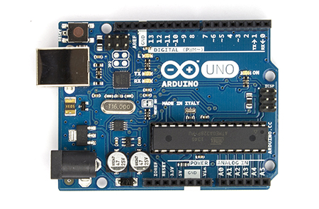
Front of an Arduino Uno development board.
Source: http://www.arduino.cc/en/Main/arduinoBoardUno
Overview
There are four main topics:
  1. How to source the parts (parts list)
  2. Determing the IR codes by reverse engineering
  3. Programming the Arduino to pulse the IR LED in response to signals from a control computer
  4. Performing speech recognition in C# and communicating with the Arduino over a virtual COM port
Parts list
  • Arduino Uno - Rev 3
  • 38 kHz IR Reciever
    • Available from various; I used the Radioshack 276-640 (which does not look like it does in the picture), but there are many pin-compatible replacements.  For example the GP1UX311QS from AdaFruit or Digikey.
  • High-output 5mm IR Led
  • Computer running Windows with attached microphone
    • Vista or Windows 7 are supported out-of-box (I think)
    • Windows XP is supported if you also have Office XP, which is needed to install the speech recognition framework; see this Microsoft support article
  • Solderless breadboard and hookup wires
  • Resistors: 1 kOhm and 330 Ohm
  • Normal LED (optional, for testing)
  • Television (or any remote-controllable device that uses IR communication)
Reverse Engineering the IR Codes
To reverse engineer the IR codes, I used a modified version of the circuit and Arduino sketch ("Arduino program") available at LadyAda's tutorial on IR sensors.  Source code for my modified version is available at this link.

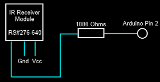
Circuit for IR Receiver
That solution requires direct access to digital input pins which are realized by a line of code which reads: if(PIND & (1 << ledPin)),where ledPin = 2.  This reads direct from the digital pin by using the PIND register.  The bits of PIND correspond to the state of the digital input pins.  When Digital input pin 2 is high, the logical and of PIND2 with 0x00000100, that is, PIND & 0x00000100 returns 1 while when it is low it returns 0.  This this way, the digital state of the pin can be accessed manually.  More documentation on this (and a few related techniques) is available at: http://www.arduino.cc/en/Reference/PortManipulation

IR communication is very simple and occurs by sending a pattern of pulse sequences.  The IR LED is either in the state OFF or PULSED.  When it is OFF, the IR LED is simply powered down.  When it is PULSED, the IR LED is being rapidly switched on and off at 38 kHz.  The duration of PULSED and OFF states defines a command.  For example, all the commands used by my Toshiba remote start with: PULSED for 8620 [us], then OFF for 4240 [us], then PULSED for 600 [us], then OFF for 580 [us], then PULSED for 480 [us], ..., etc.

To determine the needed IR pulse sequences, I picked up my TV's remote and pointed it at the IR receiver on my breadboard.  Pushing the button causes the Arduino to report the pulse sequence measured via Serial communication.  Using the Serial Monitor, I pushed each button 10 times and averaged the pulse squence durations to obtain an average code.  I measured the codes for the numeric keys (0-9), Power, Mute, Closed Captions (CC) and Sleep.

Programming the Arduino to Pulse the IR LED
The circuit to pulse the IR LED is quite simple.  Simply wire the positive (+) terminal of the IR LED to Pin 8 of the Arduino and the negative (-) terminal to a 330 Ohm resistor running to ground (see schematic below).  With the IR LED I used, with a forward voltage of 1.2 [V] and a rated current of 100 [mA], this requires a 11.5 [mA] draw from the Arduino pin (10x less than the rated IR LED voltage).  This limits the communication range to about 1-2 feet.  A better solution would probably be to control a larger amount of current with MOSFET transistor gated from the Arduino.
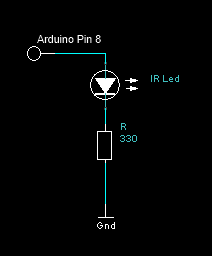
IR Output Circuit
Pulsing the IR Led at 38 kHz with a 50% duty cycle for a duration is easily accomplished by the Arduino directly.  The tutorial at LadyAda's blog shows how to produce this signal with the central insight being that the the digitalWrite(...) call takes 3 [us] to complete.  A pulse can then be easily generated with the following code:
void pulseIR(long time)
{
    cli();  //Disable interrupts
    while( time > 0 )
    {
        digitalWrite(IRled_out, HIGH);
        delayMicroseconds(10);
        digitalWrite(IRled_out, LOW);
        delayMicroseconds(10);
        time -= 26; 
    }
    sei();  //Enable interrupts
}

As I mentioned, IR communication occurs by sending a specific pattern of pulse sequences.  From my reverse engineering, I determined that each of the sequences had 69 PULSED or OFF states in their sequence.  (The encoding may vary in your system).  Since space is a little limited on the Arduino board, I used a tricky bit of encoding.  I noticed that the first 35 states and the last 7 states always have the same pattern no matter what button is pressed.  In this case, the differences between different buttons occurred only at 29 of the middle durations and in every case it led to a pulse 1080 [us] longer.  These can be efficiently encoded in an 32-bit integer (uint32_t) with each bit corresponding to one of the middle pulses (state 36 through 64).  If the pulse is 1080 [us] longer than the minimal length, the bit is set to 1; otherwise to zero.  The "consensus" code (corresponding to the minimal duration observed at each of the 69 states) is hard coded into memory and 1080 [us] is added to the state duration if the bit at the (i-35)th position in the encoding integer is 1.

In the main loop, the program waits for a byte to be transferred over the virtual serial port (COM3 on my computer) created by the Arduino USB interface corresponding to one of the commands.  (For example, I encoded numbers 1-9 to correspond to commands 0-8, number 0 to command 9, Power to 10, Mute to 11, CC to 12, and Sleep to 13).  The full source code for this sketch is shown below:
//The minimal pulse sequence (in units of 20 [us])
uint16_t consensus[] = { 431,211,29,24,29,24,29,24,29,24,29,24,29,24,29,77,29,24
,29,77,29,77,29,77,29,77,29,77,29,77,29,24,29,77,29,24,29,24,29,24,29,24,29,24,29,
24,29,24,29,24,29,24,29,24,29,24,29,24,29,24,29,77,29,24,29,77,29,1901,431};

//Number of pulses in the consensus sequence
uint16_t numConsensus = 69;

//A buffer to store the command sequence to send
uint16_t commandSeq[69];

uint16_t signalOffset = 35;      //Number of pulse durations at the
                                 // start of a message that is always
                                 // the same no matter what button
                                 // was pushed

uint16_t numSignalCodes = 14 ;  //Number of known codes (1, 2, ... 9, 0, 
                                //POWER, MUTE, CC, SLEEP)
uint32_t signalCodes[] = { 290717697,290521092,290455557,289734672,
                           289669137,289472532,289406997,286588992,286523457,
                           290783232,273744132,274006272,4198677,272892177};


const int IRled_out = 8;  //Digital pin driving the IR LED

void setup(void)
{
  //Set pin 8 to output
  pinMode(IRled_out, OUTPUT);
    
  Serial.begin(9600);
  Serial.println("Beginning Toshiba IR Commander");
}

void sendCommand(uint16_t signalCodeIndex)
{  
  if( signalCodeIndex >= numSignalCodes )
    return;
    
  uint32_t
  mask = 1;
  digitalWrite(IRled_out, LOW);
  
  //Set up the timing pattern using the
  // consensus sequence and signal-encoding
  // 32-bit integer.  Do this first to avoid
  // doing it in the time-critical loop.
  for(uint16_t i = 0; i < numConsensus; i++)
  {
     commandSeq[i] = consensus[i];
     if( i >= signalOffset )
     {
       if( mask & signalCodes[signalCodeIndex] )
         commandSeq[i] += 54;
       mask <<= 1;
     }
     commandSeq[i] *= 20;  //Scale factor (consensus sequence is
                           // stored in units of 20 [us]
  }
  
  //Modulate the signal out
  for(uint16_t i = 0; i < numConsensus; i++)
  {
    if( i & 1 )
      delayMicroseconds(commandSeq[i]);
    else
      pulseIR(commandSeq[i]);
  }
  
  //Make sure the IR LED is shut down (it already
  // should be, this is just a precaution)
  digitalWrite(IRled_out, LOW);
}

void loop(void)
{
  //Check to see if a command has been sent over
  // the serial port; if so and it is in range
  // send the appropriate code
  uint16_t toSend = (uint16_t)Serial.read();
  if( toSend < numSignalCodes )
  {
    sendCommand(toSend);
  }

  //Ensure the IR LED is off after send the sequence
  // (should already be true, but this is protective)
  digitalWrite(IRled_out, LOW);
  
  //If there are more messages, send them after a short delay
  // otherwise delay for 1 second
  if( Serial.available() == 0 )
    delay(1000);
  else
    delay(50);
}

void pulseIR(long time)
{
  cli();  //Disable interrupts
  while( time > 0 )
  {
    digitalWrite(IRled_out, HIGH);
    delayMicroseconds(10);
    digitalWrite(IRled_out, LOW);
    delayMicroseconds(10);
    time -= 26; 
  }
  sei();  //Enable interrupts
}

Speech Recognition and Virtual Serial Communication
Speech recognition is readily accomplished using the System.Speech.Recognition namespace under .NET 4.0 (possibly lower versions).  Full source code is available at this link.  I wanted to set up a system so that I could easily change channels and toggle TV power and mute state easily.  The sketch of the grammar I wanted to use is:
  1. Set channel to [number] [number] [number] (e.g. "set channel to 0 4 3", to set to channel 43)
  2. Tune network to [name of channel] (e.g. "tune network to Comedy Central")
  3. "Toggle Power"
  4. "Toggle Mute"
  5. "Toggle Closed Captions"
During development, I found that occasionally the recognition engine responded to background noise or speech not directed to the system, so I also enabled a "Pause Recognition" and "Resume Recognition" to toggle the system into/out of a waiting state.

C# readily supports construction of these grammars.  Here is the code that sets up the command grammar:
public static Grammar buildCommandGrammar()
{
    //Define a list of numbers
    Choices numbers = new Choices(new string[] { "zero", "one", "two",
                                    "three", "four", "five", "six", 
                                    "seven", "eight", "nine" });
    
    GrammarBuilder numberElement = new GrammarBuilder(numbers);
    
    //Build the set channel phrase
    GrammarBuilder setChannelPhrase = new GrammarBuilder("Set channel to");
    setChannelPhrase.Append(numberElement);
    setChannelPhrase.Append(numberElement);
    setChannelPhrase.Append(numberElement);
    
    //Build the choices for channel names
    Choices channelNameChoices = new Choices();
    foreach(string key in channelNameMap.Keys )
        channelNameChoices.Add(key);
    
    GrammarBuilder channelNamePhrase = new GrammarBuilder("Tune network to");
    channelNamePhrase.Append(channelNameChoices);
    
    GrammarBuilder mutePhase = new GrammarBuilder("Toggle Mute");
    GrammarBuilder ccPhase = new GrammarBuilder("Toggle Closed Captions");
    GrammarBuilder powerPhase = new GrammarBuilder("Toggle Power");
    GrammarBuilder terminatePhrase = new GrammarBuilder("Terminate Program");
    
    GrammarBuilder pauseRecognitionPhrase = new GrammarBuilder("Pause Recognition");
    GrammarBuilder resumeRecognitionPhrase = new GrammarBuilder("Resume Recognition");
    
    Choices mainChoices = new Choices(new GrammarBuilder[] { 
                                        setChannelPhrase,
                                        channelNamePhrase, 
                                        mutePhase, 
                                        ccPhase, 
                                        powerPhase, 
                                        terminatePhrase, 
                                        pauseRecognitionPhrase, 
                                        resumeRecognitionPhrase });
    
    Grammar result = new Grammar((GrammarBuilder)mainChoices);
    result.Name = "Toshiba Choices";
    return result;
}

In that code channelNameChoices refers to a static Dictionary<string, string> that maps channels names (e.g. "The Weather Channel") to a space-delimited command sequence macro (e.g. "0 3 1", which sets the TV to chanel 31).  For example:
static Dictionary<string, string> channelNameMap = new Dictionary<string, string>();
{
    { "Fox News", "0 6 0" },
    { "The Weather Channel", "0 3 1"},
    { "Spike", "0 3 8"}
};

To support the channels I commonly watch, I downloaded the list of TV channels for my area from my provider's website and parsed them into the channelNameChoices table (see the loadNetworks method).

Finally, speech is monitored by running the following loop:
static void parseSpeech(SerialPort port)
{
    //Set up the recognition engine
    SpeechRecognitionEngine engine = new SpeechRecognitionEngine();
    loadNetworks("Networks.txt");
    engine.LoadGrammar(buildCommandGrammar());
    engine.SetInputToDefaultAudioDevice();
    
    //Set up speech synthesizer
    SpeechSynthesizer synth = new SpeechSynthesizer();
    synth.SetOutputToDefaultAudioDevice();
    
    synth.Speak("Recognition engine online");
    
    RecognitionResult result = null;
    bool actionsOn = true;
    
    //Loop while the port is open
    while( port.IsOpen )
    {
        //Try to recognize
        result = engine.Recognize();
        
        //If null, speech detected, but not consistent
        // with the defined grammar
        if( result == null )
            Console.WriteLine("Failed to recognize");
        else
        {
            Console.WriteLine(result.Text);
            
            //Convert the speech to a command macro
            byte[] cmdArray = null;
            if( result.Text == "Toggle Mute")
                cmdArray = getCommandArray("MUTE");
            else if( result.Text == "Toggle Power")
                cmdArray = getCommandArray("POWER");
            else if( result.Text == "Toggle Closed Captions")
                cmdArray = getCommandArray("CC");
            else if( result.Text.StartsWith("Set channel to") )
                cmdArray = parseSetChannelCommand(result.Text);
            else if( result.Text.StartsWith("Tune network to") )
                cmdArray = parseTuneNetworkCommand(result.Text);
            else if( result.Text == "Resume Recognition")
            {
                synth.Speak("Ready for commands");
                actionsOn = true;
            }
            else if( result.Text == "Pause Recognition" )
            {
                synth.Speak("Acknowledged, standing by.");
                actionsOn = false;
            }
            else if( result.Text == "Terminate Program" && actionsOn )
            {
                synth.Speak("Acknowledged, terminating.");
                break;
            }
            
            //Run the macro unless recognition has been paused
            if( cmdArray != null && actionsOn )
            {                    
                port.Write(cmdArray, 0, cmdArray.Length);
            }
        }
    }
    synth.Speak("Recognition engine offline");
}

I found it was helpful to also include audio feedback for the Pause Recognition and Resume Recognition commands.  For other commands ("tune network to [...]") there is the feedback of the TV doing what I ordered it to do, but for the pause/resume commands there is only a single internal state transition.  It's nice to have the audio confirmation that those command were implemented.  I used the SpeechSynthesizer (in the System.Speech.Synthesis namespace) to give a brief confirmation message when those commands were understood by the recognition engine.

Communication with the Arduino is very simply.  Here is the code I used to open a SerialPort (in the System.IO.Ports namespace) on COM3 (the Arduino virtual port*) at 9600 baud and the (very simple) code to handle incoming data from the Arduino:
public static void openPort()
{
    port = new SerialPort("COM3", 9600);
    port.Open();
    if( !port.IsOpen )
        throw new InvalidOperationException("Port not opened");
    
    //Hook the recieve module
    port.DataReceived += OnRecv;
    
    //Enable reset
    port.DtrEnable = true;
}

public static void OnRecv(object sender, SerialDataReceivedEventArgs args)
{
    Console.Write(port.ReadExisting());
}

*The Arduino port may vary by system (many others report COM4).  Check Device Manager to be sure.

As a microphone source, I used a very old Logitech QuickCam Zoom (a desk-mounted webcam).  Acceptable speech recognition performance was achieved with this set-up.  A headset mic would probably yield better performance, but would be less portable (I like entering my study and being able to simply say "Toggle Mute" to take Fox News or CNN off of mute without needing to put on a headset mic).  However, due to the limited vocabulary and simple syntax of the recognition grammar, recognition quality was usually quite good.

Disclaimers and statements
I am not affiliated Arduino or any of the retailers mentioned above.  I have not accepted compensation in any form from any organization in support of this project.  Use this information at your own risk.  I am not responsible for any adverse effects your use of this information causes.