
Upload a new sketch to a standalone ATmega328 (pre-loaded with an Arduino bootloader) using an existing Arduino Uno without removing the existing ATmega chip from my Uno.
This is useful because:
- You won't need to buy an external AVR programmer (this method is very low cost!)
- It doesn't require constant removal of the on-Arduino ATmega328 chip to "directly" use the Tx/Rx lines (because those pins will eventually break
Anyway, some trial and error over the course of an hour or so revealed that uploading sketches to an external ATmega is very simple. For this, you will need:
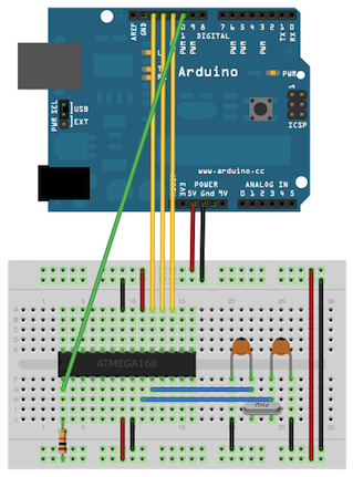
- An Arduino Uno (mine is rev 3)
- An ATmega328 microprocessor pre-loaded with Arduino bootloader (I bought this one, preloaded with the Uno optiboot bootloader, from Sparkfun).
- A 16 MHz crystal oscillator
- Two 22 pF ceramic capacitors
- A 10 kOhm resistor
- A capacitor with capacitance > 10 uF (I used a 22 uF capacitor, but others have reported success with 10 uF capacitors).
- Pins 7 and 20 to +5V
- Pins 8 and 22 to Gnd
- Pin 1 (reset) to +5V through a 10 kOhm resistor
- Crystal oscillator to pins Z and K
- A 22 pF capacitor connecting each pin of the oscillator to ground
Next, connect your Arduino Uno to the USB port of your computer, open up Arduino IDE (version 1.0.1 or later), select the ArduinoISP sketch from the examples file (see image below) and upload this to your Arduino like you would any other sketch.
 |
| How to find the ArduinoISP sketch |
Now disconnect your Uno from the USB port (thereby disconnecting power) and wire the following connections:
- Arduino pin 10 to Standalone Pin 1 [Reset]
- Arduino pin 11 to Standalone Pin 17
- Arduino pin 12 to Standalone Pin 18
- Arduino pin 13 to Standalone Pin 19
If your arduino auto-resets when a serial connection is established (e.g. when you load a new program), you will need to disable it. There is a page describing this, but for my Uno, the simplest solution was to put a 22 uF capacitor between the reset and Gnd pins. Others have reported success with other capacitor values; the most common value I have seen is 10 uF.
Your Arduino is now ready to act as a programmer for the standalone ATmega chip. Plug it back into the USB port. Load the sketch you want to program the standalone ATmega chip with into the Arduino IDE (I recommend "blink" while you are trying this out for the first time). Set the IDE to use the programmer "Arduino as ISP" as in the image below:
 |
| Configure Arduino IDE to use the connected Arduino as an ISP |
Then upload the sketch using the programmer:
 |
| Upload your sketch using the connected (ArduinoISP) programmer |
The Rx/Tx lines should flash for a few seconds on your Arduino board. When it finishes, your standalone ATmega should be programmed with the desired sketch. The Arduino will continue to be programmed with the ArduinoISP sketch.
Disconnect power (the USB plug) from both circuits and remove the jumpers between the Arduino and the standalone ATmega chip. Remove the 22 uF capacitor between the Reset/Gnd pins on your Arduino to return it back to a state where you can re-program it away from the ArduinoISP state.
Hopefully, you now know how to program an external ATmega chip by (completely reversibly!) converting your Arduino to an ISP. Please feel free to leave comments if (a) this worked for you, (b) this didn't work for you and tell us what you're seeing, or (c) if you've noticed any mistakes in my instructions (though I have striven to eliminate errors).
Standard disclaimers and statements
I am not affiliated Arduino or any of the retailers mentioned above. I have not accepted compensation in any form from any organization in support of this project. Use this information at your own risk as there is always a possibility of undetected inaccuracies. I am not responsible for any adverse effects your use of this information causes including, but not limited to, damage to hardware or humans.