I've been experimenting with an
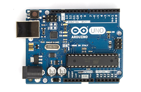
Arduino Uno (pictured below) for the past few days. The Arduino is a microprocessor development board based on the ATmega 328 chip. Today I'll show how to create a
voice-controlled TV remote using the Arduino interfaced with a simple program written in C#.
 |
Front of an Arduino Uno development board.
Source: http://www.arduino.cc/en/Main/arduinoBoardUno |
Overview
There are four main topics:
- How to source the parts (parts list)
- Determing the IR codes by reverse engineering
- Programming the Arduino to pulse the IR LED in response to signals from a control computer
- Performing speech recognition in C# and communicating with the Arduino over a virtual COM port
Parts list
- Arduino Uno - Rev 3
- 38 kHz IR Reciever
- Available from various; I used the Radioshack 276-640 (which does not look like it does in the picture), but there are many pin-compatible replacements. For example the GP1UX311QS from AdaFruit or Digikey.
- High-output 5mm IR Led
- Computer running Windows with attached microphone
- Vista or Windows 7 are supported out-of-box (I think)
- Windows XP is supported if you also have Office XP, which is needed to install the speech recognition framework; see this Microsoft support article
- Solderless breadboard and hookup wires
- Resistors: 1 kOhm and 330 Ohm
- Normal LED (optional, for testing)
- Television (or any remote-controllable device that uses IR communication)
Reverse Engineering the IR Codes
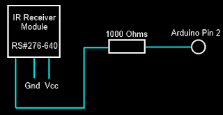
To reverse engineer the IR codes, I used a modified version of the circuit and Arduino sketch ("Arduino program") available at
LadyAda's tutorial on IR sensors. Source code for my modified version is available at
this link.
 |
| Circuit for IR Receiver |
That solution requires direct access to digital input pins which are realized by a line of code which reads:
if(PIND & (1 << ledPin)),where ledPin = 2. This reads direct from the digital pin by using the PIND register. The bits of PIND correspond to the state of the digital input pins. When Digital input pin 2 is high, the logical and of PIND2 with 0x00000100, that is, PIND & 0x00000100 returns 1 while when it is low it returns 0. This this way, the digital state of the pin can be accessed manually. More documentation on this (and a few related techniques) is available at: http://www.arduino.cc/en/Reference/PortManipulation
IR communication is very simple and occurs by sending a pattern of pulse sequences. The IR LED is either in the state OFF or PULSED. When it is OFF, the IR LED is simply powered down. When it is PULSED, the IR LED is being rapidly switched on and off at 38 kHz. The duration of PULSED and OFF states defines a command. For example, all the commands used by my Toshiba remote start with: PULSED for 8620 [us], then OFF for 4240 [us], then PULSED for 600 [us], then OFF for 580 [us], then PULSED for 480 [us], ..., etc.
To determine the needed IR pulse sequences, I picked up my TV's remote and pointed it at the IR receiver on my breadboard. Pushing the button causes the Arduino to report the pulse sequence measured via Serial communication. Using the Serial Monitor, I pushed each button 10 times and averaged the pulse squence durations to obtain an average code. I measured the codes for the numeric keys (0-9), Power, Mute, Closed Captions (CC) and Sleep.
Programming the Arduino to Pulse the IR LED
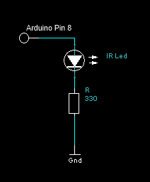
The circuit to pulse the IR LED is quite simple. Simply wire the positive (+) terminal of the IR LED to Pin 8 of the Arduino and the negative (-) terminal to a 330 Ohm resistor running to ground (see schematic below). With the IR LED I used, with a forward voltage of 1.2 [V] and a rated current of 100 [mA], this requires a 11.5 [mA] draw from the Arduino pin (10x less than the rated IR LED voltage). This limits the communication range to about 1-2 feet. A better solution would probably be to control a larger amount of current with MOSFET transistor gated from the Arduino.
 |
| IR Output Circuit |
Pulsing the IR Led at 38 kHz with a 50% duty cycle for a duration is easily accomplished by the Arduino directly. The
tutorial at LadyAda's blog shows how to produce this signal with the central insight being that the the
digitalWrite(...) call takes 3 [us] to complete. A pulse can then be easily generated with the following code:
void pulseIR(long time)
{
    cli();  //Disable interrupts
    while( time > 0 )
    {
        digitalWrite(IRled_out, HIGH);
        delayMicroseconds(10);
        digitalWrite(IRled_out, LOW);
        delayMicroseconds(10);
        time -= 26;
    }
    sei();  //Enable interrupts
}
As I mentioned, IR communication occurs by sending a specific pattern of pulse sequences. From my reverse engineering, I determined that each of the sequences had 69 PULSED or OFF states in their sequence.
(The encoding may vary in your system). Since space is a little limited on the Arduino board, I used a tricky
bit of encoding. I noticed that the first 35 states and the last 7
states always have the same pattern no matter what button is pressed.
In this case, the differences between different buttons occurred only at
29 of the middle durations and in every case it led to a pulse 1080
[us] longer. These can be efficiently encoded in an 32-bit integer
(uint32_t) with each bit corresponding to one of the middle pulses
(state 36 through 64). If the pulse is 1080 [us] longer than the
minimal length, the bit is set to 1; otherwise to zero. The "consensus"
code (corresponding to the minimal duration observed at each of the 69
states) is hard coded into memory and 1080 [us] is added to the state
duration if the bit at the (i-35)th position in the encoding integer is
1.
In the main loop, the program waits for a byte to be transferred over the virtual serial port (COM3 on my computer) created by the Arduino USB interface corresponding to one of the commands. (For example, I encoded numbers 1-9 to correspond to commands 0-8, number 0 to command 9, Power to 10, Mute to 11, CC to 12, and Sleep to 13). The full source code for this sketch is shown below:
//The minimal pulse sequence (in units of 20 [us])
uint16_t consensus[] = { 431,211,29,24,29,24,29,24,29,24,29,24,29,24,29,77,29,24
,29,77,29,77,29,77,29,77,29,77,29,77,29,24,29,77,29,24,29,24,29,24,29,24,29,24,29,
24,29,24,29,24,29,24,29,24,29,24,29,24,29,24,29,77,29,24,29,77,29,1901,431};

//Number of pulses in the consensus sequence
uint16_t numConsensus = 69;

//A buffer to store the command sequence to send
uint16_t commandSeq[69];

uint16_t signalOffset = 35;      //Number of pulse durations at the
                                 // start of a message that is always
                                 // the same no matter what button
                                 // was pushed

uint16_t numSignalCodes = 14 ;  //Number of known codes (1, 2, ... 9, 0,
                                //POWER, MUTE, CC, SLEEP)
uint32_t signalCodes[] = { 290717697,290521092,290455557,289734672,
                           289669137,289472532,289406997,286588992,286523457,
                           290783232,273744132,274006272,4198677,272892177};


const int IRled_out = 8;  //Digital pin driving the IR LED

void setup(void)
{
  //Set pin 8 to output
  pinMode(IRled_out, OUTPUT);

  Serial.begin(9600);
  Serial.println("Beginning Toshiba IR Commander");
}

void sendCommand(uint16_t signalCodeIndex)
{
  if( signalCodeIndex >= numSignalCodes )
    return;

  uint32_t
  mask = 1;
  digitalWrite(IRled_out, LOW);

  //Set up the timing pattern using the
  // consensus sequence and signal-encoding
  // 32-bit integer.  Do this first to avoid
  // doing it in the time-critical loop.
  for(uint16_t i = 0; i < numConsensus; i++)
  {
     commandSeq[i] = consensus[i];
     if( i >= signalOffset )
     {
       if( mask & signalCodes[signalCodeIndex] )
         commandSeq[i] += 54;
       mask <<= 1;
     }
     commandSeq[i] *= 20;  //Scale factor (consensus sequence is
                           // stored in units of 20 [us]
  }

  //Modulate the signal out
  for(uint16_t i = 0; i < numConsensus; i++)
  {
    if( i & 1 )
      delayMicroseconds(commandSeq[i]);
    else
      pulseIR(commandSeq[i]);
  }

  //Make sure the IR LED is shut down (it already
  // should be, this is just a precaution)
  digitalWrite(IRled_out, LOW);
}

void loop(void)
{
  //Check to see if a command has been sent over
  // the serial port; if so and it is in range
  // send the appropriate code
  uint16_t toSend = (uint16_t)Serial.read();
  if( toSend < numSignalCodes )
  {
    sendCommand(toSend);
  }

  //Ensure the IR LED is off after send the sequence
  // (should already be true, but this is protective)
  digitalWrite(IRled_out, LOW);

  //If there are more messages, send them after a short delay
  // otherwise delay for 1 second
  if( Serial.available() == 0 )
    delay(1000);
  else
    delay(50);
}

void pulseIR(long time)
{
  cli();  //Disable interrupts
  while( time > 0 )
  {
    digitalWrite(IRled_out, HIGH);
    delayMicroseconds(10);
    digitalWrite(IRled_out, LOW);
    delayMicroseconds(10);
    time -= 26;
  }
  sei();  //Enable interrupts
}
Speech Recognition and Virtual Serial Communication
Speech recognition is readily accomplished using the System.Speech.Recognition namespace under .NET 4.0 (possibly lower versions). Full source code is available at
this link. I wanted to set up a system so that I could easily change channels and toggle TV power and mute state easily. The sketch of the grammar I wanted to use is:
- Set channel to [number] [number] [number] (e.g. "set channel to 0 4 3", to set to channel 43)
- Tune network to [name of channel] (e.g. "tune network to Comedy Central")
- "Toggle Power"
- "Toggle Mute"
- "Toggle Closed Captions"
During development, I found that occasionally the recognition engine responded to background noise or speech not directed to the system, so I also enabled a "Pause Recognition" and "Resume Recognition" to toggle the system into/out of a waiting state.
C# readily supports construction of these grammars. Here is the code that sets up the command grammar:
public static Grammar buildCommandGrammar()
{
    //Define a list of numbers
    Choices numbers = new Choices(new string[] { "zero", "one", "two",
                                    "three", "four", "five", "six",
                                    "seven", "eight", "nine" });

    GrammarBuilder numberElement = new GrammarBuilder(numbers);

    //Build the set channel phrase
    GrammarBuilder setChannelPhrase = new GrammarBuilder("Set channel to");
    setChannelPhrase.Append(numberElement);
    setChannelPhrase.Append(numberElement);
    setChannelPhrase.Append(numberElement);

    //Build the choices for channel names
    Choices channelNameChoices = new Choices();
    foreach(string key in channelNameMap.Keys )
        channelNameChoices.Add(key);

    GrammarBuilder channelNamePhrase = new GrammarBuilder("Tune network to");
    channelNamePhrase.Append(channelNameChoices);

    GrammarBuilder mutePhase = new GrammarBuilder("Toggle Mute");
    GrammarBuilder ccPhase = new GrammarBuilder("Toggle Closed Captions");
    GrammarBuilder powerPhase = new GrammarBuilder("Toggle Power");
    GrammarBuilder terminatePhrase = new GrammarBuilder("Terminate Program");

    GrammarBuilder pauseRecognitionPhrase = new GrammarBuilder("Pause Recognition");
    GrammarBuilder resumeRecognitionPhrase = new GrammarBuilder("Resume Recognition");

    Choices mainChoices = new Choices(new GrammarBuilder[] {
                                        setChannelPhrase,
                                        channelNamePhrase,
                                        mutePhase,
                                        ccPhase,
                                        powerPhase,
                                        terminatePhrase,
                                        pauseRecognitionPhrase,
                                        resumeRecognitionPhrase });

    Grammar result = new Grammar((GrammarBuilder)mainChoices);
    result.Name = "Toshiba Choices";
    return result;
}
In that code
channelNameChoices refers to a static
Dictionary<string, string> that maps channels names (e.g. "The Weather Channel") to a space-delimited command sequence macro (e.g. "0 3 1", which sets the TV to chanel 31). For example:
static Dictionary<string, string> channelNameMap = new Dictionary<string, string>();
{
    { "Fox News", "0 6 0" },
    { "The Weather Channel", "0 3 1"},
    { "Spike", "0 3 8"}
};
To support the channels I commonly watch, I downloaded the list of TV channels for my area from
my provider's website and parsed them into the
channelNameChoices table (see the
loadNetworks method).
Finally, speech is monitored by running the following loop:
static void parseSpeech(SerialPort port)
{
    //Set up the recognition engine
    SpeechRecognitionEngine engine = new SpeechRecognitionEngine();
    loadNetworks("Networks.txt");
    engine.LoadGrammar(buildCommandGrammar());
    engine.SetInputToDefaultAudioDevice();

    //Set up speech synthesizer
    SpeechSynthesizer synth = new SpeechSynthesizer();
    synth.SetOutputToDefaultAudioDevice();

    synth.Speak("Recognition engine online");

    RecognitionResult result = null;
    bool actionsOn = true;

    //Loop while the port is open
    while( port.IsOpen )
    {
        //Try to recognize
        result = engine.Recognize();

        //If null, speech detected, but not consistent
        // with the defined grammar
        if( result == null )
            Console.WriteLine("Failed to recognize");
        else
        {
            Console.WriteLine(result.Text);

            //Convert the speech to a command macro
            byte[] cmdArray = null;
            if( result.Text == "Toggle Mute")
                cmdArray = getCommandArray("MUTE");
            else if( result.Text == "Toggle Power")
                cmdArray = getCommandArray("POWER");
            else if( result.Text == "Toggle Closed Captions")
                cmdArray = getCommandArray("CC");
            else if( result.Text.StartsWith("Set channel to") )
                cmdArray = parseSetChannelCommand(result.Text);
            else if( result.Text.StartsWith("Tune network to") )
                cmdArray = parseTuneNetworkCommand(result.Text);
            else if( result.Text == "Resume Recognition")
            {
                synth.Speak("Ready for commands");
                actionsOn = true;
            }
            else if( result.Text == "Pause Recognition" )
            {
                synth.Speak("Acknowledged, standing by.");
                actionsOn = false;
            }
            else if( result.Text == "Terminate Program" && actionsOn )
            {
                synth.Speak("Acknowledged, terminating.");
                break;
            }

            //Run the macro unless recognition has been paused
            if( cmdArray != null && actionsOn )
            {
                port.Write(cmdArray, 0, cmdArray.Length);
            }
        }
    }
    synth.Speak("Recognition engine offline");
}
I found it was helpful to also include audio feedback for the Pause Recognition and Resume Recognition commands. For other commands ("tune network to [...]") there is the feedback of the TV doing what I ordered it to do, but for the pause/resume commands there is only a single internal state transition. It's nice to have the audio confirmation that those command were implemented. I used the SpeechSynthesizer (in the System.Speech.Synthesis namespace) to give a brief confirmation message when those commands were understood by the recognition engine.
Communication with the Arduino is very simply. Here is the code I used to open a SerialPort (in the System.IO.Ports namespace) on COM3 (the Arduino virtual port*) at 9600 baud and the (very simple) code to handle incoming data from the Arduino:
public static void openPort()
{
    port = new SerialPort("COM3", 9600);
    port.Open();
    if( !port.IsOpen )
        throw new InvalidOperationException("Port not opened");

    //Hook the recieve module
    port.DataReceived += OnRecv;

    //Enable reset
    port.DtrEnable = true;
}

public static void OnRecv(object sender, SerialDataReceivedEventArgs args)
{
    Console.Write(port.ReadExisting());
}
*The Arduino port may vary by system (many others report COM4). Check Device Manager to be sure.
As a microphone source, I used a very old Logitech QuickCam Zoom (a desk-mounted webcam). Acceptable speech recognition performance was achieved with this set-up. A headset mic would probably yield better performance, but would be less portable (I like entering my study and being able to simply say "Toggle Mute" to take Fox News or CNN off of mute without needing to put on a headset mic). However, due to the limited vocabulary and simple syntax of the recognition grammar, recognition quality was usually quite good.
Disclaimers and statements
I am not affiliated Arduino or any of the retailers mentioned above. I have
not accepted compensation in any form from any organization in support of this project. Use this information at your own risk. I am not responsible for any adverse effects your use of this information causes.


